- Our Purpose
- Our Science and Technology
- Join Our Team
- Partner with Us
- Community and Education

- Experimenting with Electromagnetic Waves
We see, communicate, manufacture, and explore using the waves on the electromagnetic spectrum, including those in the visible, microwave, radio, and x-ray frequencies. Using your smartphone, you will explore how colors combine, and measure: the absorbance and reflection of light; your pulse using light: and the strength of microwaves that carry Wi-Fi signals.
Experimenting with Electromagnetic Waves Part 1
Experimenting with Electromagnetic Waves Part 2
- Core Competencies
- Unique Facilities
- Lab Directed Research and Development
- Institutional Initiatives
- Research Integrity
- S&T Highlights
- Recognition
- Director's Awards
- Journal Covers
- A Look Back
- LLNL Institutes/Centers
- Current and Former Lawrence Fellows
- Lawrence Fellowship: Learn more and apply
- Career Development & Network Activities
- Life Around the Lab
- Lawrence Livermore Postdoc Association
- Research SLAM!
- Internally Sponsored Internships
- Externally Sponsored Internships
- Fun with Science
- Application Process
- Camp Activities
- Biotech Summer Experience
- Manufacturing Workshop
- STEM with Phones
- STEM San Joaquin
- Science on Saturday
- Teacher Research Academy
- Physics with Phones Introduction and Links
- Understanding Motion
- Exploring Acceleration
- Exploring Friction & Mechanics
- The Physics of Rotational Motion
- Moment of Inertia
- Investigating Impulse and Momentum
- The Science of Collisions
- Measuring the Pressure Around Us
- A Foundation for Understanding Waves
- Mechanical Waves and Sound
- Exploring Magnetic Fields in the World Around You
- Making Digital Measurements and Quantifying Uncertainty
- Virtual Discovery Center
- Virtual Tours and Class Visits
- Ambassador Lecture Series
- Faculty Sabbatical Program
- Science Education
- Postdoc Opportunities
- Student Opportunities
- About Us: Academic Engagement Office
- Innovation and Partnerships Office
- Research Library
- Earth Science
- Physics & Engineering
- Science Kits
- Microscopes
- Science Curriculum and Kits
- About Home Science Tools
Science Projects > Physics & Engineering Projects > Electromagnetism Experiments

Electromagnetism Experiments
Electric current flowing through a wire creates a magnetic field that attracts ferromagnetic objects, such as iron or steel. This is the principle behind electromagnets and magnetic levitation trains. It allows cranes to pick up whole cars in the junkyard and makes your doorbell ring. You can read about it here , and then watch it work when you do these experiments. (Adult supervision recommended.)
Electromagnetic Experiments
-Electromagnetic Suction -Electromagnet -Magnetic Propulsion
Experiment 1: Electromagnetic Suction
A single strand of wire produces only a very weak magnetic field, but a tight coil of wire (called a solenoid ) gives off a stronger field. In this experiment, you will use an electric current running through a solenoid to suck a needle into a straw!
What You Need:
- drinking straw
- 5 feet insulated copper wire
- 6-volt battery
What You Do:
1. Make your solenoid. Take five feet of insulated copper wire and wrap it tightly around the straw. Your solenoid should be about 3 inches long, so you’ll have enough wire to wrap a couple of layers.
2. Trim the ends of the straw so they just stick out of the solenoid.
3. Hold the solenoid horizontally and put the end of the needle in the straw and let go. What happens?
4. Now strip an inch of insulation off each end of the wire and connect the ends to the 6-volt battery. Insert the needle part-way in the straw again and let go. This time what happens? (Don’t leave the wire hooked up to the battery for more than a few seconds at a time – it will get hot and drain the battery very quickly)
When you hooked your solenoid up to a battery, an electric current flowed through the coils of the wire, which created a magnetic field. This field attracted the needle just like a magnet and sucked it into the straw. Try some more experiments with your solenoid – will more coils make it suck the needle in faster? Will it still work with just a few coils? Make a prediction and then try it out!
Experiment 2: Electromagnet
As you saw in the last experiment, electric current flowing through a wire produces a magnetic field. This principle comes in very handy in the form of an electromagnet. An electromagnet is wire that is tightly wrapped around a ferromagnetic core. When the wire is connected to a battery, it produces a magnetic field that magnetizes the core. The magnetic fields of the core and the solenoid work together to make a very strong magnet. The best part about it is that the magnetic force stops when the electricity is turned off! Try it yourself with this experiment:
- large iron nail
1. Tightly wrap the wire around the nail to make a solenoid with a ferromagnetic core. If you have enough wire, wrap more than one layer. (If your nail fits inside the straw from the last experiment, you can use that solenoid instead of rewrapping the wire.)
2. Try to pick up some paperclips with the wire-wrapped nail. Can you do it?
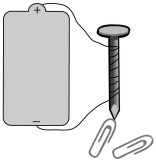
3. Strip an inch of insulation off each end of the wire.
4. Hook up the wire to the battery and try again to pick up the paperclips with the nail. This time the electricity will create a magnetic field and the nail will attract paperclips! (Don’t leave the wire hooked up to the battery for more than a few seconds at a time – it will get hot and drain the battery very quickly.)
Experiment some more with your electromagnet. Count how many paperclips it can pick up. If you coil more wire around it will it pick up more paperclips? How many paperclips can you pick up if you only use half as much wire? What would happen if you used a smaller battery, like a D-size? Predict what you think will happen and then try it out!
Experiment 3: Magnetic Propulsion
A maglev (magnetically levitated) train doesn’t use a regular engine like a normal train. Instead, electromagnets in the track produce a magnetic force that pushes the train from behind and pulls it from the front. You can get an idea of how it works using some permanent magnets and a toy car.
- 3 bar magnets
1. Tape a bar magnet to a small toy car with the north pole at the back of the car and the south pole at the front.
2. Put the car on a hard surface, like a linoleum floor or a table. Hold a bar magnet behind the car with the south pole facing the car. As you move it near the car, what happens? The south pole of your magnet repels the north pole of the magnet on the car, making the car move forward.
3. Have someone else hold another magnet in front of the car, with the north pole facing the car. Does the car move faster with one magnet ‘pushing’ from behind and the other magnet ‘pulling’ from ahead?
In our example, the permanent magnets have to move with the car to keep it going. In a maglev track, though, the electromagnets just change their poles by changing the direction of the electric current. They stay in the same spot, but their poles change as the train goes by so it will always be repelled from the electromagnets behind it and attracted by the electromagnets in front of it!

Need Supplies?
Buy an Electromagnetism Experiment Kit!
Physics & Engineering
Welcome! Read other Physics & Engineering related articles or explore our Resource Center, which consists of hundreds of free science articles!
Shop for Physics Supplies!
Home Science Tools offers a wide variety of Physics products and kits. Find physics & engineering tools, equipment, STEM kits & more for kids and adults.
Related Articles

Science Fair Projects for 8th Graders
Science Fair Projects for 8th Graders As kids reach the 8th grade, their exposure to science goes up a notch. Equipped with basic knowledge, they can begin to explore more complicated concepts and satisfy their curiosity for deeper answers to the 'whys' and 'hows' of...

Science Fair Projects for 7th Graders
Science Fair Projects for 7th Graders Science fair projects for 7th graders are a step up in complexity. Because 7th graders have a better grasp of science concepts, they’re expected to practice the scientific method in the way they approach their experiments–which...

Home Science Experiments for Preschoolers
Home Science Experiments for Preschoolers Home science experiments for preschoolers are a great way to pique your child’s curiosity, teach them valuable knowledge, and allow them to have some fun in the comfort of their own home. There are plenty of activities your...

Easy Science Fair Projects for Kids
Easy Science Fair Projects for Kids Science fairs are a long-standing tradition that provide kids with the opportunity to better understand practical concepts in fun and innovative ways. The great thing about the experiments presented at these events is that they...

How to Make a Pollinator Hotel
Have you ever wondered how you can help provide habitat for pollinators like honey bees and butterflies in your back yard? Learn how to make a pollinator hotel with this step-by-step guide and lesson. Pollinators are animals that help move pollen. Most pollinators are...
JOIN OUR COMMUNITY
Get project ideas and special offers delivered to your inbox.
- Skip to primary navigation
- Skip to main content
- Skip to primary sidebar
Teaching Expertise
- Classroom Ideas
- Teacher’s Life
- Deals & Shopping
- Privacy Policy
20 Engaging Activities To Teach Electromagnetism
April 11, 2023 // by Nicole Neumann
Are you teaching about the electromagnetic spectrum this year? Look no further than the activities below to find something engaging to get your class excited to learn! Electromagnetism is the interaction of electric currents or fields. With quirky crafts, hands-on experiments, and more, you’ll quickly be able to help your students get to grapple with this somewhat tricky content. Let’s get stuck into exploring 20 fantastic activities!
1. Electromagnetism Escape Room
This immersive experience allows your students to demonstrate their knowledge of electromagnetic energy in an engaging way. Students need to work together to ask questions and conduct an investigation in order to free themselves from an escape room.
Learn More: Kesler Science
2. Drawing Magnetic Field Lines

During this science experiment, students will perform a little bit of magic! Magnetic field lines are invisible but with this activity, you can make them appear! With only a few supplies and clear directions, this is a simple yet engaging activity to enjoy with your students.
Learn More: National Mag Lab

3. Electromagnetic Induction Experiment
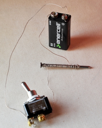
This science project involves cutting wire and twisting it around a nail to create a solenoid. This will allow your students to witness the phenomenon of currents that are carried by electricity.
Learn More: Education
4. Digital Interactive Lesson
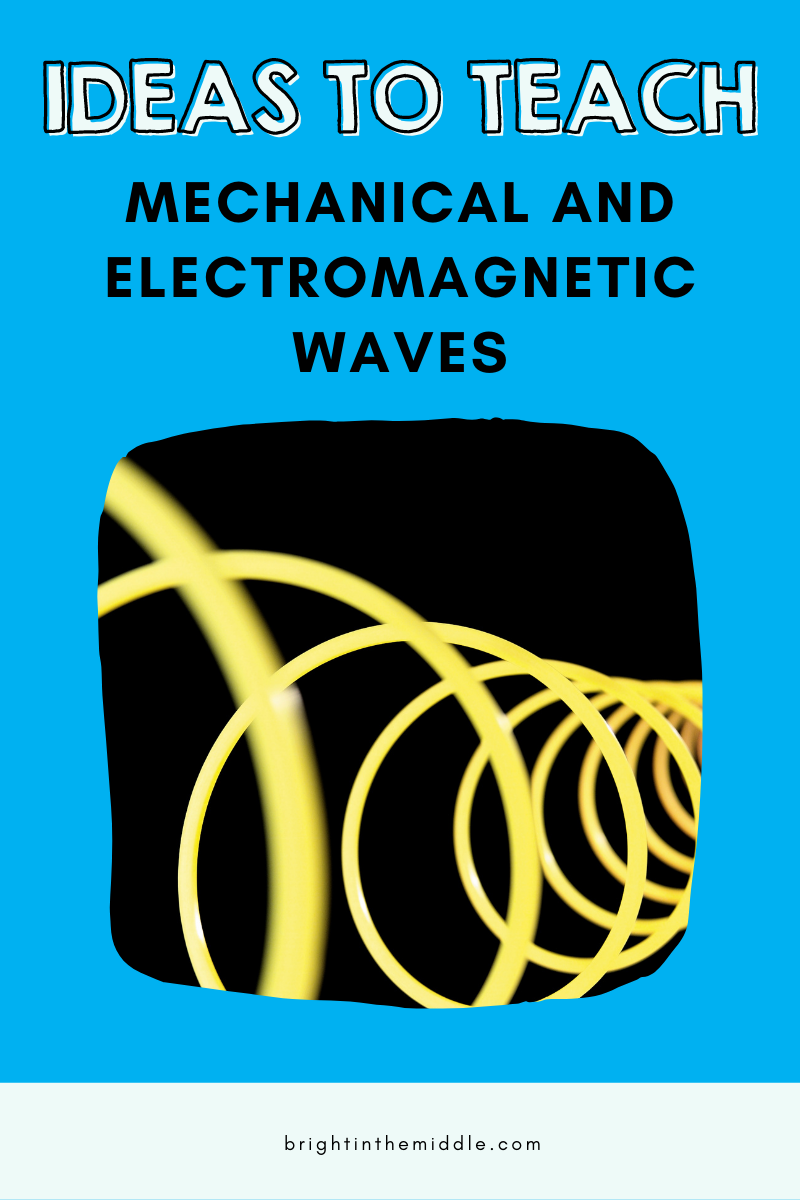
Ditch the worksheets for an interactive lesson that gives your students a chance to learn a whole lot of new information but not feel overwhelmed. This lesson explores the differences and similarities between mechanical and electromagnetic waves.
Learn More: Bright in the Middle
5. Activity Book

Get your students interested in electromagnetism at a young age! This activity book which is designed for younger learners includes coloring pages, connect the dots, and word searches about electromagnetism. It’s free, easy to download, and available in both English and Spanish.
6. Copper Battery Train
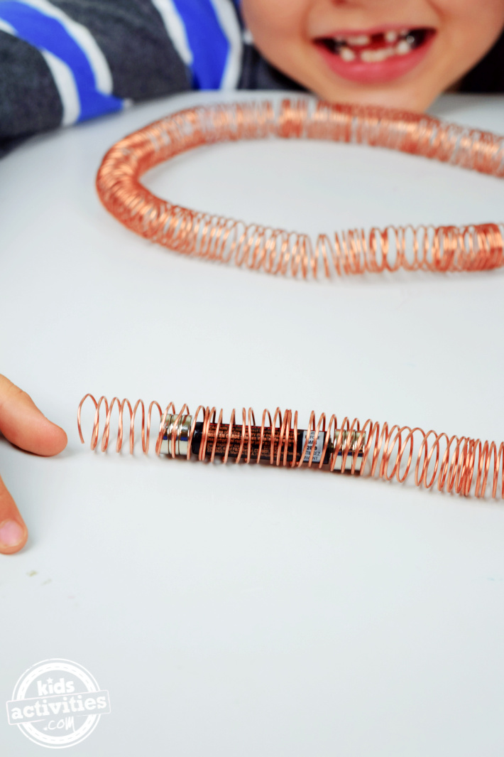
our kids will start by wrapping copper wire around a marker to create a long coil. Next, they will make the train by placing three magnets on each side of the battery. This STEM activity is a simple science experiment that’s easy to arrange and fun to play with.
Learn More: Kids Activities
7. The Electromagnetic Clothesline

Students will begin this activity by exploring the meaning of several key terms including Hz. Afterward, they will set up the logarithmic scale of the clothesline. Then, learners can observe the outcome and discuss the results with a partner.
Learn More: Serp Media
8. Create an Electromagnet

In this hands-on activity, students will work in teams to investigate the properties of electromagnets. They will create their very own small electromagnets. This is a very detailed lesson plan with learning objectives and standards included to make setup easy!
Learn More: Stem Library Lab
9. Electromagnetism Suction

With only four supplies needed and a list of only four steps, this short but sweet experiment will get your students engaged in electromagnets in no time! Students will use an electric current running through a solenoid to suck a needle into a straw.
Learn More: Home Science Tools
10. Microwave Experiment

Your students will take a deeper look at a traditional household item; microwaves. Microwaves are a form of electromagnetic radiation with wavelengths that are shorter than radio waves.
Learn More: Growing with Science
11. Waves Close Reading

Close reading is a great way for students to closely examine the meaning of a text by looking at the language used. This specific packet is a great way to introduce, review, and reinforce all of the jargon around electromagnetic and mechanical waves.
Learn More: The Trendy Science Teacher
12. Student-Led Station Lab

The station labs consist of eight different activities. During the Explore It lab, students will identify the elements that each star is comprised of. During the Watch It lab , students will watch a five-minute video about the electromagnetic spectrum.
13. Electromagnetic Spectrum Doodle Notes

Doodle notes are visual aids that increase student concept retention, focus, creativity, and engagement. This set includes 1 fill-in-the-blank doodle note, PowerPoint slides, example notes, and even a student quiz.
Learn More: The Morehouse Magic
14. Whodunnit Activity

This fun and engaging criminal investigation activity will certainly liven up learning about the electromagnetic spectrum. Students must work in teams to answer 10 questions. If they correctly answer the questions, they receive a clue and can progress to the next question.
Learn More: Clark Creative Education
15. Science Maze

This worksheet is designed to help kids understand the difference between the size of each type of radiation in the electromagnetic spectrum. It might appear simple but it will challenge your students. An answer key is included for easy grading.
Learn More: Science of Things
16. Task Cards

Your students will learn the basics of the electromagnetic spectrum by answering the questions on each of the task cards. This activity can be used in the classroom for review, partner work, stations, and independent work.
Learn More: The Science Duo
17. Color by Number

This activity is ready to print and be used! Students will answer 12 questions that relate to electromagnetic waves. Once they answer the questions, they can use their answers to color.
Learn More: Morpho Science
18. Match the Words

This simple worksheet requires students to match the vocabulary word to where it’s missing in a sentence. This could be a great start or end to a lesson. Additionally, it could work well as a review before a test.
Learn More: Teaching Packs
19. Electromagnetic Spectrum Crafts

This is a unique and artistic take on learning about the electromagnetic spectrum. Students can create water molecules, atoms, and waves by sewing and crafting with materials such as pipe cleaners and yarn.
Learn More: Lollies or Candy
20. Sketch Notes

A graphic organizer is a great way to introduce or review key vocabulary words and this one is no different. Students will work on the electromagnetic spectrum. There is even room for visual learners to draw pictures and for early finishers to color.
Learn More: Creativity Meets Cognition
Description This is a simple animation representing an electromagnetic wave. The green vectors show the fluctuation of the electric field, the red vectors show the fluctuation of the magnetic field.
- Lecture Demonstration Manual
- Lab Manuals
- Instructional Videos
- PhotoSpheres
You are here
Table of contents.
- Experiment 1 - Magnetic Fields of Coils and Faraday's Law
Experiment 2 - Microwave Optics
- Experiment 3 - Geometrical Optics
- Experiment 4 - Physical Optics
- Experiment 5 - Fluids and Thermodynamics
- Experiment 6 - The Photoelectric Effect
- Experiment 7 - Radioactivity
- DC analog microammeter
- Microwave transmitter
- Microwave receiver
- Power supply
- Four-arm track with protractor and scale
- Ring stand with clamp
- Banana leads
- Triangular aluminum screens
- Flat aluminum screen
- Flat lucite screen
- Single slit
- Double slits
- Assortment of materials: ceiling tiles, wood, metal plates
INTRODUCTION
In this experiment, you will test several optical aspects of electromagnetic waves such as polarization, reflection, and interference. The electromagnetic spectrum covers a wide range of frequencies. Visible light has a frequency of the order of 10 14 Hz and wavelengths between 400 and 700 nm (1 nm = 10 −9 m). Other well-known parts of the spectrum include radio waves (with frequencies near 10 6 Hz) and microwaves (with frequencies around 10 10 Hz and wavelengths of a few centimeters). Microwaves can be generated easily and are particularly suited for laboratory investigations.
POLARIZATION, REFLECTION, AND ABSORPTION OF MICROWAVES
Electromagnetic waves consist of position-dependent and time-dependent electric and magnetic fields which are perpendicular to each other. These waves propagate in a direction perpendicular to both fields. In this experiment, we consider microwaves produced by a transmitter whose axis is vertical. The electric fields of these microwaves are therefore linearly polarized in the vertical plane and travel in the horizontal direction.
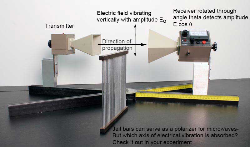
A receiver which detects such microwaves measures only the component of the incident electric field parallel to its axis. If the angle between the incident electric field (of amplitude \(E_0\) and the receiver axis is \(\theta\), then the parallel component of the field has amplitude \(E_0\cos\theta\), as shown in the figure above. Since the intensity of a wave is proportional to the square of its amplitude, the intensity \(I\) measured by the receiver is related to the intensity \(I_0\) of the incident wave by
\begin{eqnarray} I &=& I_0 \cos^2\theta. \label{eqn_Malus} \end{eqnarray}
Eq. \eqref{eqn_Malus} is known as Malus' Law and tells us how the intensity varies with angle between the transmitter and receiver.
A wave incident on a metallic surface will be reflected after striking the surface. The law of reflection states that the angle of reflection \(\theta_{\textrm{r}}\) is equal to the angle of incidence \(\theta_{\textrm{i}}\): \(\theta_{\textrm{r}} = \theta_{\textrm{i}}\). Note that both angles are measured with respect to the normal to the surface.
Microwaves which impinge upon an opaque material are either reflected by, transmitted through, or absorbed by the material. Let us denote the reflected, transmitted, absorbed, and total electric-field amplitudes by \(R\), \(T\), \(A\), and \(E\), respectively. The law of energy conservation tells us that the total energy of the incident microwaves is equal to the sum of the reflected, transmitted, and absorbed energies. Since energy is directly proportional to intensity and therefore proportional to the square of the electric-field amplitude, it follows that
\begin{eqnarray} E^2 &=& R^2 + T^2 + A^2 \end{eqnarray}
\begin{eqnarray} A^2 &=& E^2 - R^2 - T^2. \label{eqn_Absorbed} \end{eqnarray}
Thus, the percentage \(f_{\textrm{A}}\) of the incident microwave intensity absorbed by a material is
\begin{eqnarray} f_{\textrm{A}} &=& [(E^2 - R^2 - T^2) /E^2] \times 100\%. \label{eqn_fAbsorbed} \end{eqnarray}
INTERFERENCE
When two separate waves occupy the same region of space, they combine with each other. According to the superposition principle , the displacement of the resultant wave is equal to the sum of the displacements of the individual waves. If the crests of the individual waves coincide with each other, then the amplitude of the resultant wave is a maximum, and the waves are said to undergo constructive interference . On the other hand, if the crest of one wave coincides with the trough of the other wave, then the amplitude of the resultant wave is zero at all points, and the waves undergo destructive interference . Waves that interfere constructively “build each other up” and have a maximum intensity , while those that interfere destructively “cancel each other out” and have a minimum intensity .
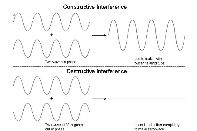
In this experiment you will build a device called a Michelson interferometer that splits a wave into two waves and then recombines the waves after they have traveled different distances. If the extra distance traveled by one of the two waves (called the path difference ) is equal to an integral multiple of one wavelength (i.e., 0, \(\lambda\), \(2\lambda\), etc.), constructive interference results, and the combined waves be measured to have a large intensity, as shown in the figure above. Conversely, if the path difference is equal to an odd integral multiple of a half wavelength (i.e., \(\lambda/2\), \(3\lambda/2\), \(5\lambda/2\), etc.), destructive interference occurs, and the waves will cancel when they overlap and produce zero intensity.
INITIAL SETUP
You may find one of two types of microwave receiver/transitter setups at your station. Both of these setups use Gunn diodes to generate microwaves.
The most modern version, Pasco WA 9314B, is the easiest to use, and has a self-contained meter. Align the receiver horn facing the transmitter horn, and plug the transmitter in to turn it on. On the receiver, turn the intensity knob from “off” to “30”. Adjust the variable sensitivity knob for a full scale reading. You can increase the sensitivity later in the experimet if needed. When finished with the experiment, unplug the transmitter, and turn off the receiver.
The older Gunn diode unit uses a DC power supply for the transmitter, and a separate meter for the receiver. Be careful of the polarity from the power supply to the transmitter. The positive (red) connector of the power supply's output must be hooked to the positive (red) connector of the transmitter's input, or the diode will be destroyed. To adjust this device, place the receiver directly opposite the transmitter, and set the meter to minimum sensitivity. Turn on the power supply, and slowly increase the voltage until the diode begins to generate microwaves. You will notice that a further increase in voltage increases the output power until a plateau voltage is reached. After this point, an increase in voltage does not increase the output power. The transmitter should be operated at the beginning of this plateau. Never exceed 15 Volts DC , as doing so would destroy the Gunn diode.
The microwave receiver consists of a crystal diode which produces a current when aligned parallel to the electric field of the incident microwaves. The diode is not sensitive to microwaves whose electric field is perpendicular to its axis. The current from the diode is read by the horn. Be careful of the polarity between the receiver and the meter. The positive (red) connector of the receiver's output must be hooked to the positive (red) connector of the meter's input, or the meter movement may be destroyed. Never connect the receiver to the power supply , as this will destroy the diode instantly.
The microwaves emerging from the transmitter are linearly polarized in the vertical plane, and the receiver is sensitive only to the electric-field component parallel to its axis. Begin by recording the wavelength of the microwaves produced by the transmitter. Stand the transmitter and receiver vertically, with the two horns facing and approximately 30 cm apart from each other, as shown below.
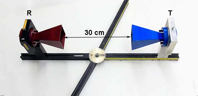
Connect the receiver to the meter, and align the transmitter and receiver horns such that the meter reading is a maximum. Adjust the sensitivity of the meter to read a convenient value (e.g., 100) at the maximum, and take this orientation of the receiver to be \(\theta\) = 0° in Eq. \eqref{eqn_Malus}. Rotate the receiver in 5° increments, and record its reading for angles between 0° and 90° in the “Data” section. Since the meter measures the relative electric-field amplitude of the microwaves, you must square all readings to obtain the relative intensity \(I\). Plot the experimental values of \(I\) as a function of \(\theta\).
Using Eq. \eqref{eqn_Malus}, plot the theoretical values of \(I\) as a function of \(\theta\). Comment on the extent to which your data agrees with or differs from Malus' Law.
Return the receiver to its vertical position. Place the polarization grid between the transmitter and receiver, as shown below.
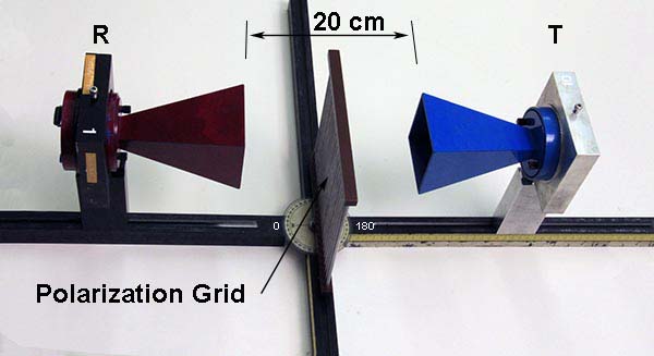
Rotate the polarization grid until it blocks all incoming microwaves, and note the orientation of the bars with respect to the incident electric field (i.e., either parallel or perpendicular). Explain what is happening. (This is not obvious. It has nothing to do with waves “squeezing between the bars”, but has much to do with the fact that the bars are conductors. You may wish to refer to your data in step 6 for a hint.)
The reflection of microwaves by a full reflector (i.e., an aluminum plate) is measured with the setup shown below.
Place the transmitter approximately 15 cm from the reflector at an angle of incidence \(\theta_{\textrm{i}}\) = 30° (as measured by the protractor on the four-armed base). Vary the angle of the receiver (as measured by the protractor) until the meter reading is a maximum. Record this angle of reflection \(\theta_{\textrm{r}}\). Repeat the procedure for angles of incidence of 45° and 60°, measure the corresponding angles of reflection, and check the validity of the law of reflection.
Arrange the setup for absorption and reflection as shown below.
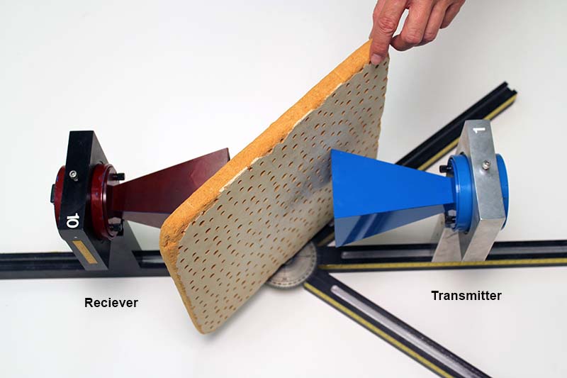
Place the transmitter and receiver horns facing and approximately 10 cm from each other. Adjust the sensitivity of the meter to read a convenient value (e.g., 100). This is the maximum electric-field amplitude (\(E\,\)) detected by the receiver. Place at least four different materials (two metal, one nonmetal, and lucite) at an angle of 45° with respect to the beam, and record the transmitted amplitude (\(T\,\)) for each material. Rotate the receiver so that it is at a right angle to the transmitter (as measured by the protractor), place the materials at an angle of 45° with respect to the beam, and record the reflected amplitude (\(R\,\)) for each material. Using Eq. \eqref{eqn_fAbsorbed}, calculate the percentage \(f_{\textrm{A}}\) of the incident microwave intensity absorbed by each material.
The wavelength \(\lambda\) of the microwaves can be measured with the Michelson interferometer shown below. (An interferometer is a device that can be used to measure lengths or changes in length with great accuracy by means of interference effects.)
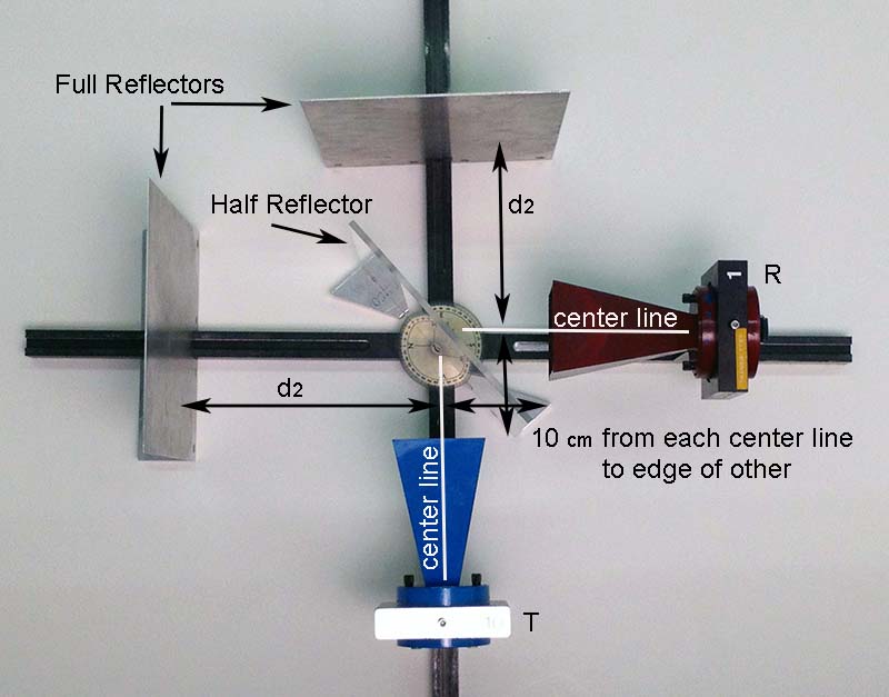
The transmitter and receiver horns should each be approximately 10 cm from the center of the track. Place the two full (aluminum) reflectors at right angles to each other (as measured by the protractor) and at distances \(d_1\) and \(d_2\) from the center of the track. Place the half (lucite) reflector at an angle of 45° with respect to the incident beam. Adjust \(d_1\) (the position of the full reflector opposite the receiver) until the receiver reading is a minimum. Next, adjust \(d_1\) (the position of the full reflector opposite the transmitter) until the receiver reading is a minimum. Then vary \(d_1\) between 15 cm and 40 cm, and record at least 15 values of \(d_1\) for which the receiver output is a minimum . Knowing that the distance between adjacent minima is \(\lambda/2\), calculate \(\lambda\) for each pair of adjacent minima, and determine the average wavelength. Compare this value with the wavelength recorded in step 1.
Wavelength of microwaves =
Amplitude at \(\theta\) = 0° =
Amplitude at \(\theta\) = 5° =
Amplitude at \(\theta\) = 10° =
Amplitude at \(\theta\) = 15° =
Amplitude at \(\theta\) = 20° =
Amplitude at \(\theta\) = 25° =
Amplitude at \(\theta\) = 30° =
Amplitude at \(\theta\) = 35° =
Amplitude at \(\theta\) = 40° =
Amplitude at \(\theta\) = 45° =
Amplitude at \(\theta\) = 50° =
Amplitude at \(\theta\) = 55° =
Amplitude at \(\theta\) = 60° =
Amplitude at \(\theta\) = 65° =
Amplitude at \(\theta\) = 70° =
Amplitude at \(\theta\) = 75° =
Amplitude at \(\theta\) = 80° =
Amplitude at \(\theta\) = 85° =
Amplitude at \(\theta\) = 90° =
Intensity at \(\theta\) = 0° =
Intensity at \(\theta\) = 5° =
Intensity at \(\theta\) = 10° =
Intensity at \(\theta\) = 15° =
Intensity at \(\theta\) = 20° =
Intensity at \(\theta\) = 25° =
Intensity at \(\theta\) = 30° =
Intensity at \(\theta\) = 35° =
Intensity at \(\theta\) = 40° =
Intensity at \(\theta\) = 45° =
Intensity at \(\theta\) = 50° =
Intensity at \(\theta\) = 55° =
Intensity at \(\theta\) = 60° =
Intensity at \(\theta\) = 65° =
Intensity at \(\theta\) = 70° =
Intensity at \(\theta\) = 75° =
Intensity at \(\theta\) = 80° =
Intensity at \(\theta\) = 85° =
Intensity at \(\theta\) = 90° =
Plot the experimental graph of \(I\) as a function of \(\theta\) using one sheet of graph paper at the end of this workbook. Remember to label the axes and title the graph.
Plot the theoretical graph of \(I\) as a function of \(\theta\) using the same sheet of graph paper. Remember to label the axes and title the graph.
Which orientation of the bars blocks all incoming microwaves? Why?
Angle of reflection for \(\theta_{\textrm{i}}\) = 30° =
Angle of reflection for \(\theta_{\textrm{i}}\) = 45° =
Angle of reflection for \(\theta_{\textrm{i}}\) = 60° =
Maximum electric-field amplitude =
Material 1 =
Material 2 =
Material 3 =
Material 4 =
Transmitted amplitude for material 1 =
Transmitted amplitude for material 2 =
Transmitted amplitude for material 3 =
Transmitted amplitude for material 4 =
Reflected amplitude for material 1 =
Reflected amplitude for material 2 =
Reflected amplitude for material 3 =
Reflected amplitude for material 4 =
Percentage of microwave intensity absorbed by material 1 =
Percentage of microwave intensity absorbed by material 2 =
Percentage of microwave intensity absorbed by material 3 =
Percentage of microwave intensity absorbed by material 4 =
Positions at which receiver output is a minimum =
Wavelength for each pair of adjacent minima =
Average wavelength =
Percentage difference between average wavelength and value recorded in step 1 =

COMMENTS
Jul 8, 2021 · Electromagnets and Electromagnetic Fields. 1. Strength of an Electromagnet. In the What Factors Affect the Strength of an Electromagnet? lesson, students make simple electromagnets each using a battery, wire, and a nail (a classic experiment!), and then explore how different variables may affect the strength of an electromagnet. For example ...
We see, communicate, manufacture, and explore using the waves on the electromagnetic spectrum, including those in the visible, microwave, radio, and x-ray frequencies. Using your smartphone, you will explore how colors combine, and measure: the absorbance and reflection of light; your pulse using light: and the strength of microwaves that carry ...
Electromagnetic Experiments-Electromagnetic Suction-Electromagnet-Magnetic Propulsion. Experiment 1: Electromagnetic Suction. A single strand of wire produces only a very weak magnetic field, but a tight coil of wire (called a solenoid) gives off a stronger field. In this experiment, you will use an electric current running through a solenoid ...
Apr 11, 2023 · 10. Microwave Experiment. Your students will take a deeper look at a traditional household item; microwaves. Microwaves are a form of electromagnetic radiation with wavelengths that are shorter than radio waves. Learn More: Growing with Science. 11. Waves Close Reading
The wavelength of an electromagnetic wave is inversely proportional to its frequency. So waves with high frequency have short wavelengths, and waves with low frequency have long wavelengths. Electromagnetic waves interact with materials in different ways, depending on the nature of the material and the frequency of the electromagnetic wave.
apparatus yourself. In most student physics labs, if you do this well, then you should expect to get “good results”. This is certainly the case for most of the experiments in Physics 375. However, the real world is often too complex for a simple theory to capture all of the details that can be seen in an experiment.
They may pinch your fingers or crack. Keep them away from small children, pets, credit cards, and pacemakers. In the Science Buddies project Human-Powered Energy, you can learn about the basics of magnetic induction, or how moving magnets can be used to generate an electric current. The detailed physics of how a changing… Read more
Electromagnetic waves are transverse waves with a wide range of properties and uses. All objects are continually absorbing and emitting infrared radiation, affecting their temperatures.
AP Physics 2 Refraction Problem; ... The Millikan Oil-Drop Experiment; ... This is a simple animation representing an electromagnetic wave. The green vectors show the ...
In this experiment, you will test several optical aspects of electromagnetic waves such as polarization, reflection, and interference. The electromagnetic spectrum covers a wide range of frequencies. Visible light has a frequency of the order of 10 14 Hz and wavelengths between 400 and 700 nm (1 nm = 10 −9 m).